
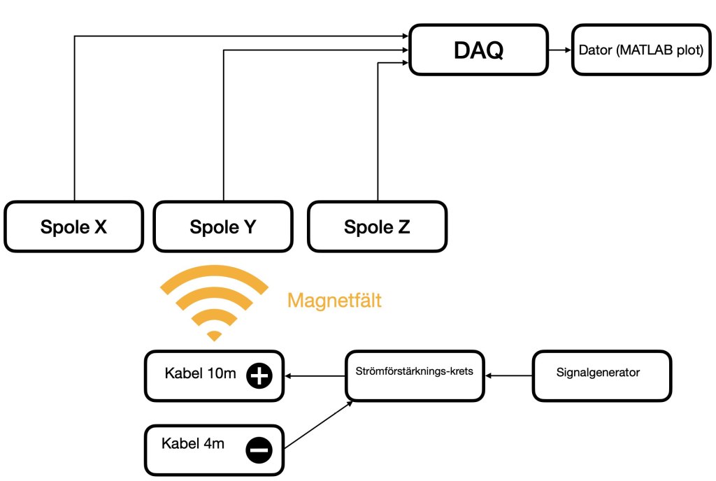
The project concerns how a system can be created to detect electromagnetic fields that are created around a cable.
The goal was to investigate how the location of the soil affects the electromagnetic field and thus the detection ability of an underwater cable. The problem is that the current going to the soil induces its own field and thus there is a risk that the fields cancel each other out. The method chosen to determine the design of the system capable of detecting electromagnetic fields was a Design-Build-Test-Learn cycle. The project was carried out in three iterations to then lead up to a final test where the impact of the grounding was investigated.
During Iteration 1, a MATLAB model was created to investigate the performance of the coil in terms of the number of turns and the diameter of the core. After the simulation, a coil was created in reality. An iron core was turned, and the copper wire with a diameter of 0.5 mm was wound onto it. A total of 443 turns were wound. A circuit was created where a current of 0.1 A was sent. The coil was initially connected to an oscilloscope, which was then replaced with a DAQ to see if any signal was detected.
Further development of the coil design was carried out during Iteration 2. Increasing the number of turns was expected to result in a higher voltage amplitude so the coil was wound with 2000 turns. To wind more turns in a shorter time a fixture was created. The copper wire was reduced to 0.2 mm to accommodate more turns. In total two layers or 1910 turns were wound. The tests
were conducted in the same manner as in Iteration 1, and the data was presented in the form of an FFT diagram. Additionally, a non-inverting amplifier was used to examine whether the signal needed to be lifted above the noise floor of the DAQ.
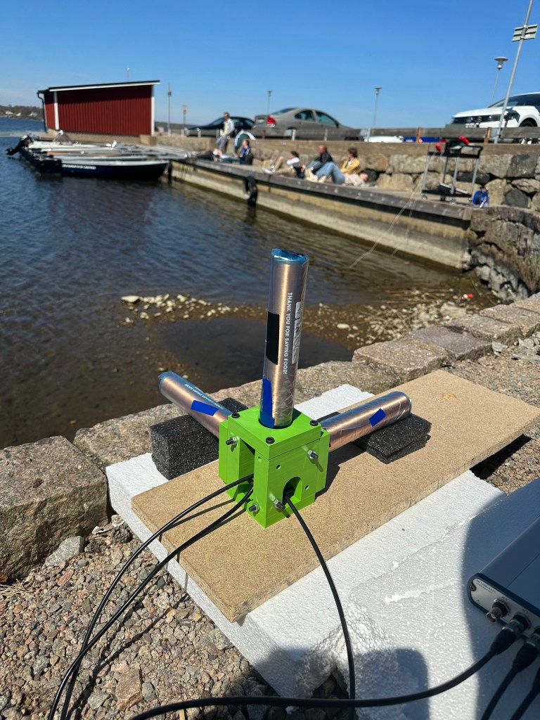
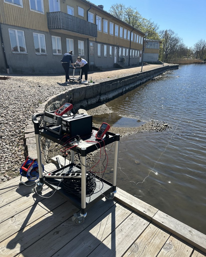
After Iteration 3, the final design of the coil was completed. Three coils were wound with four layers or 3920 turns. Furthermore, it was determined that signal amplification was required to enable detection at greater distances. This was achieved using a transistor configuration. The coils were connected together to allow testing in three dimensions. Tests of the grounding’s impact were conducted near the water. Initially, a test was carried out with the steel rods placed apart from each other. The steel rods were aligned in the second test to examine if this placement affected the detection capability. A final measurement was performed to examine if the correct signal was detected by switching the transmitted frequency.
During Iteration 1 testing, the signal at a frequency of 124 Hz was measured to be 21 μV at a distance of 10 cm. In Iteration 2, the simulation results were reduced to 6.5% of the original values. The second coil was tested at two distances. At the first distance of 10 cm, the measured signal was 20 μV. The second distance of 12 cm resulted in a signal of 5.3 μV. Multiple tests were conducted on the third coil to assess the improvement in behavior. At a distance of 1.2 m, a signal of 123 μV was detected. At a distance of 2 m, the voltage was 41 μV. The results of the grounding’s impact test indicated that the placement of grounding affects the detection capability. When the steel rods were aligned with each other, the strength that the coils could detect decreased.
Some potential areas for further development include creating a system that can determine the distance to the cable based on the strength of the electromagnetic field. Testing on an actual NKT cable could be conducted, as it was not done during the project. Signal post-processing could be enhanced through the use of filters or similar techniques. Additionally, implementing the system on an underwater vehicle would be an exciting avenue for further development.
By Luc Jennerhed, Jonna Nilsson and Hannes Wolf
Cooperation with

